In the following analysis it has been assumed that:
* 1) The material is homogeneous, isotropic and has the same value for Youngs Modulus in both tension and compression.
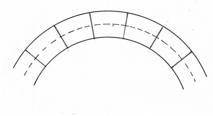
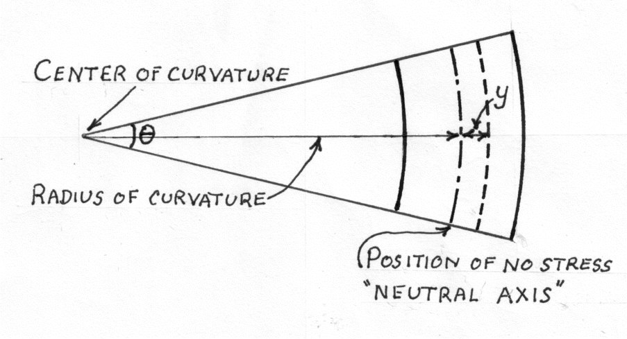
* 2) The beam is initially straight and all longitudinal filaments bend into circular arcs with a common centre of curvature.
* 3) Transverse cross-sections remain plane and perpendicular to the neutral surface after bending.
* 4) The radius of curvature is large compared the dimensions of the cross section.
* 5) The stress is purely longitudinal and local effects near concentrated loads are neglected.
* 6) That the stresses are within the elastic limit of the material and no permanent distortion of the material takes place.
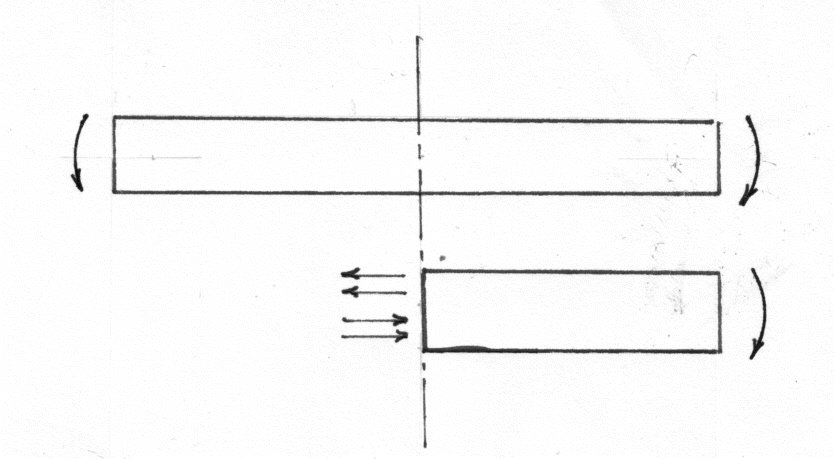 The above diagram shows a beam which is subject to a bending force. If the beam is to bend, there is only one way in which it can happen. If we examine a small bit under stress it will look like this.
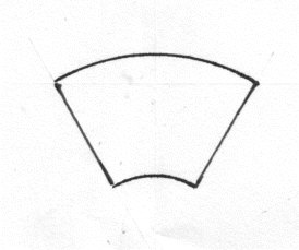
Of course it can still be joined up to the sections next to it because the plane sections remain plane.


\;-\;\theta \, R}{\theta \, R}")

")

From this it is apparent that
 is constant for any given bending moment. Stress is directly proportional to the distance from the Neutral Axis. |Therefore in the interests of both weight reduction and economy, material is concentrated at the greatest possible distance from the neutral axis. Hence the universal adoption of "I" section steel girders. If
  is an element of cross section at a distance y from the neutral axis XX then for pure bending thee net normal force on the cross section must be zero.
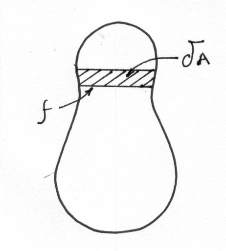


 and is called the moment of inertia of the section or second moment of area. Equations (5) and (10) can now be combined into:- Where f is the stress at a distance y from the Neutral Axis. M is the Bending Moment, I is the Moment of area ( Sometimes called Moment of Inertia) E is Young's Modulus R is the radius of Curvature.


Tidak ada komentar:
Posting Komentar